


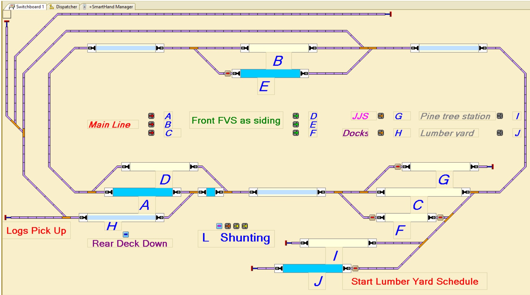
Well this has taken a long time – to work out a system to have 2 Locos driven automatically by train controller while I drive one Loco manually. I have tried all sorts of systems with all sorts of control buttons everywhere. But I found all these forms to hard to undertake and easily use. So I have come to my current system which is proving far supieror to the other things I have tried. I have created a route which I can switch with a keyboard shortcut. The route has 3 sections, each has a current sensor, with the middle of the 3 sections being either the siding or main track where a train can pass. This means when a train enters section 3 after having gone through section 1 & 2. I can decide the path through the next passing area (luckily this worked out for me with how passing sidings were located) Generally as I have learned to operate with this method I have found it very successful and easy to use.

When shunting, I have a number of single routes that are enabled with just keystroke
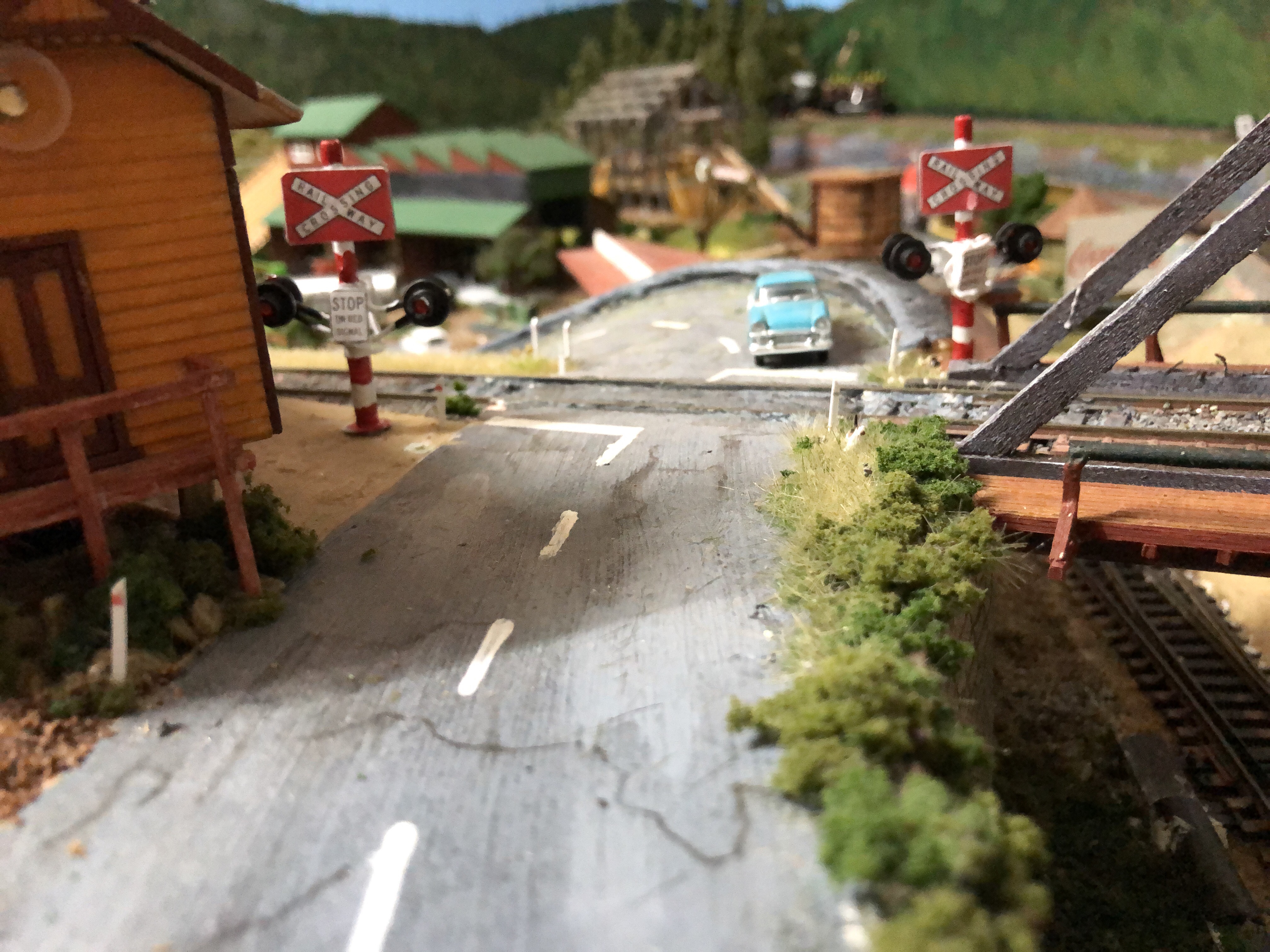
Here is a effect on gentle movement simulating wave movement of a calm sea. Once I am happy with the effect I will start to detail the ocean and wharf which will add realism to the effect.

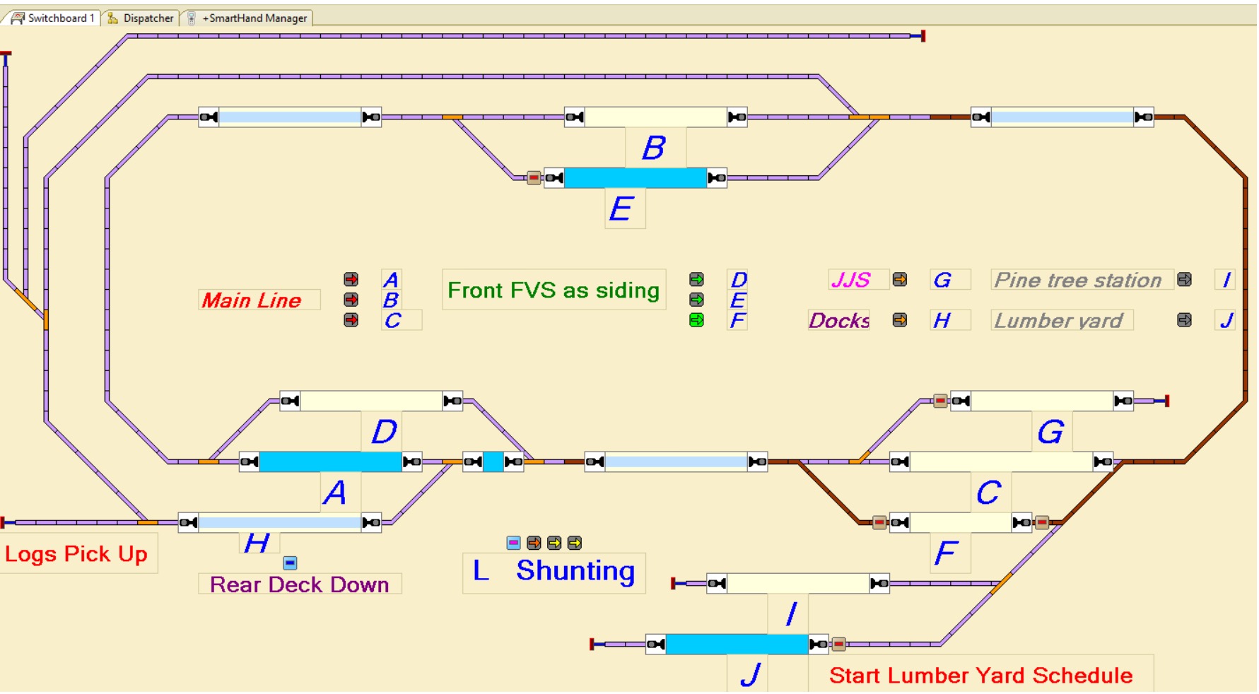
This was an interesting activity to have a go at, with one unforeseen side issue. After I had completed this, I later realised that I was going to undertake an extension to the layout, which meant I not longer had a place for the new turnout on the track plan. But I found that using Train Controller software that a new track plan could easily updated and changed to suit my system. I have since done a couple of other changes to my layout that can be incorporated as well. (Still have one more change to go) The train controller software uses Hot Keys to toggle the turnouts (as well as clicking on the turnout) and you get a visual of the computer monitor to show turnout position. I find this very good, but it is also very handy to have the old system as it can be used when I don’t have the computer on.


My system is a NCE cab system, using a AIU and Accessory Decoder CDU Solenoid Drive SX 8-Way to control turnouts and control panel. A USB interface for computer connection and BD20’s were installed as current sensors to be used for train detection. I am very happy with the NCE system and found it generally plug and play once the correct address was used, especially for the AIU (cab address 4 needed to be used). Train Controller was very easy to set up all aspects of the NCE system but needed the different cab address to get the AIU to connect.

One of the things I wanted to incorporate into the bench work was a way to do under bench work without laying on my back. While this method of pivoting up the layout has been very successful. There are small parts of the layout where I still have to reach awkwardly. Thankfully, these areas can be reached from the other side.
